RENGA ARCHI SYSTEM
Women Graduates are trained with basics in Industry application from basic science Mathematics, Physics, Chemistry
Training in application Software by Industry Professional, to train others with preparation as TRAINER to empower.
Empowering areas are ACADEMIC SERVICE-ENTREPRENEURSHIP-DESIGN SERVICE-INDUSTRIES-SOCIAL ENGINEERING
AIM of this training is to get employment directly or indirectly from Industries, Government organization either state or central bodies. Also to develop or support rural industries & other application industries either as induvial or self group
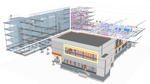
Renga
a computer-aided building design system, Renga allows you to create three-dimensional models of buildings that include engineering structures and communications, and receive drawings and specifications from them.
Renga
a computer-aided building design system, Renga allows you to create three-dimensional models of buildings that include engineering structures and communications, and receive drawings and specifications from them.
ELECTRICAL
Power supply system design
Power supply system design
Data collection and retrieval
Data collection and retrieval
Definition of loads
Definition of loads
Equipment layout
Equipment layout
Laying tracks
Laying tracks
Automatic calculations
Automatic calculations
Automatic calculation of specifications
Automatic calculation of specifications
Preparation of design and working documentation
Preparation of design and working documentation
Collaboration on a project
Collaboration on a project
Power supply system design
Power supply system design
In Renga, you can create information models of networks of internal power supply and electric lighting of buildings and structures for various purposes. Renga tools allow you to automate the actions of an engineer as much as possible in the process of laying routes for lighting and power lines, when filling the model with engineering data for the relevant section and obtaining drawing documentation.
Data collection and retrieval
Data collection and retrieval
Designing networks of internal power supply and electric lighting in Renga provides for 2 work scenarios.
In the first, the profile specialist receives a three-dimensional model from the architect or designer and begins his work on modeling the corresponding section. Collaboration mechanism is implemented in Renga complex architectural and construction system. The program allows electrical engineers to work in parallel on a project with architects and designers. The project participants work with up-to-date information on the 3D model, coordinating the decisions made in time with each other.
In the second scenario, the designer receives 2D drawings from an architect or designer, independently creates a 3D model using the provided tools, and then fills it with objects of power supply and electric lighting networks. It is possible to use 2D drawings as a background.
Definition of loads
Definition of loads
The information model allows profile specialists to enter all the necessary data for each element of the building so that in the future they can be used by all project participants. Thus, specialists in internal power supply and electric lighting networks have the opportunity to immediately obtain the required information about the purpose and dimensions of the premises, external and internal enclosing structures, materials used, the position of mines for engineering communications, and much more. Based on the data obtained, the needs of various rooms of the building in electrical systems are identified, and engineering calculations are performed, for example, determining the lighting load.
Equipment layout
Equipment layout
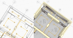
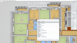
In accordance with the identified needs of various premises of the building in electrical systems, engineers select and arrange power and lighting equipment throughout the model of the designed object. One of the advantages of Renga is the independence of the work of specialists from the "blank" catalogs of objects of internal power supply and electric lighting networks. The program implements a universal tool "Styles", which allows you to create all the necessary types of equipment from any manufacturer. In a matter of minutes, by changing the parameters of the system type, the user receives the instance required in the project.
At the same time, if necessary, it is possible to import three-dimensional objects into the model, which the engineer can use in the model being created. For this, system integration with other software products and import in .ifc, .c3d, formats is provided. step, .sat, .iges, etc. In addition, Renga will present ready-made catalogs of leading manufacturers of power and lighting equipment
Laying tracks
Laying tracks
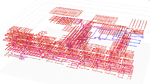
The construction of traces of electrical systems is carried out by Renga's unique tool "Automatic Routing". He independently performs the laying of cables, as well as connecting equipment to them in accordance with the rules that the engineer sets. In a special mode called "System Designer", the user shows the sequence of connecting objects, sets the offset from the level of the floor and walls, and in parallel with his actions, the corresponding power or lighting trace is built in the model. The cables specified by the designer are automatically assigned to it.
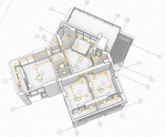
At the same time, the actions of a specialist are minimized as much as possible and the time for making a decision on the spatial configuration of network elements is reduced, since during the construction process the program takes into account the objects of the architectural section: wall, foundation, beam, column, window and door openings. As a result, in the created model, the location of all elements of electrical systems in the premises of the building, as well as their positioning relative to each other, is clearly visible. This helps to avoid mistakes when coordinating and linking sections of design and working documentation to each other
Automatic calculations
Automatic calculations
Calculation modules for networks of internal power supply and electric lighting are created in external applications and calculation complexes of partners. This allows you not to limit users in the choice of certain systems. The program allows the designer to load ready-made calculations into a tabular form and take them into account when preparing documentation.
Automatic calculation of specifications
Automatic calculation of specifications
For an accurate calculation of all elements of internal power supply and electric lighting networks, Renga has a "Specifications" tool. It automatically collects information from model objects and generates the table required by the designer according to GOST 21.110-2013, allowing you to forget about manual calculation and filling in data. Specifications are associated with the 3D model and are automatically recalculated whenever it changes
Preparation of design and working documentation
Preparation of design and working documentation
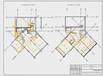
Renga is configured to issue documentation on electrical systems in accordance with the standards in force in the territory of the Russian Federation. The developed templates allow the designer to quickly and competently design drawing sheets in accordance with SPDS.
The tools provided to users make it possible to automatically generate the required plans for internal power supply and electric lighting networks in accordance with GOST 21.608-2014 and GOST 21.613-2014, where drawing scales are observed and all elements are displayed in accordance with conventionally graphic symbols (UGO).
Collaboration on a project
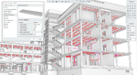
In the Renga BIM system, an architect, a designer and an internal engineering network designer work together on the same model. Each project participant can always see what changes his colleagues have made. Such work in a team helps to avoid errors associated with a mismatch between the architectural model and the design model or the model of internal engineering networks. And also reduces the time for the development and coordination of solutions.
It is convenient to organize a shared data environment with the help of a comprehensive solution from ASCON Pilot-BIM. In it, you can combine BIM models created in different systems into a single common information model using the IFC general exchange format, coordinate and exchange tasks between project participants both within the team and with colleagues who create their own sections of project documentation in other BIM systems . Information can also be exchanged with CAD systems by means of drawings in DWG/DXF format.