VARICAD 2D/3D/PDM/BOM
Women Graduates are trained with basics in Industry application from basic science Mathematics, Physics, Chemistry
Training in application Software by Industry Professional, to train others with preparation as TRAINER to empower.
Empowering areas are ACADEMIC SERVICE-ENTREPRENEURSHIP-DESIGN SERVICE-INDUSTRIES-SOCIAL ENGINEERING
VariCAD - 3D / 2D CAD software for mechanical engineering
VariCAD - 3D / 2D CAD software for mechanical engineering
VariCAD is compact, fast, easy to use, and provides everything necessary for mechanical design.
VariCAD is sold "fully loaded", including all features and functions, for one affordable price.
VariCAD - Designing Has Never Been Easier!
VariCAD Viewer - Free CAD viewer
VariCAD Viewer is a free viewer, converter and printing software working with 2D DWG, DXF, 3D STEP and 3D/2D VariCAD file formats. VariCAD viewer allows you to convert DWG to DXF and vice-versa, convert STEP to 3D IGES or STL formats, print 2D DWG, DXF or VariCAD formats and use batch print or batch conversions. VariCAD viewer offers settings of 3D display methods (like light source or perspective). 3D display can be also exported into high-resolution bitmap file.
VariCAD Viewer is a free viewer, converter and printing software working with 2D DWG, DXF, 3D STEP and 3D/2D VariCAD file formats. VariCAD viewer allows you to convert DWG to DXF and vice-versa, convert STEP to 3D IGES or STL formats, print 2D DWG, DXF or VariCAD formats and use batch print or batch conversions. VariCAD viewer offers settings of 3D display methods (like light source or perspective). 3D display can be also exported into high-resolution bitmap file.
30-Day Free License (Trial Version)
Download your free 30-day license of VariCAD and evaluate all of its powerful features prior to making your purchasing decision. The 30-day license (trial version) is fully functional for a limited period of time and is available for both Windows and Linux.
VariCAD - 3D / 2D mechanical CAD software
VariCAD - 3D / 2D mechanical CAD software
We have a simple strategy - to sell VariCAD, with all its features, for one very affordable price. VariCAD is the best value you will find anywhere for this type of modeling and designing software.
VariCAD for Windows and for Linux
A comprehensive, powerful, and easy to use 3D/2D CAD system for all aspects of mechanical engineering design. All features are included in one package.
VariCAD is compact, fast, easy to use, and provides everything necessary for mechanical design. The system contains:
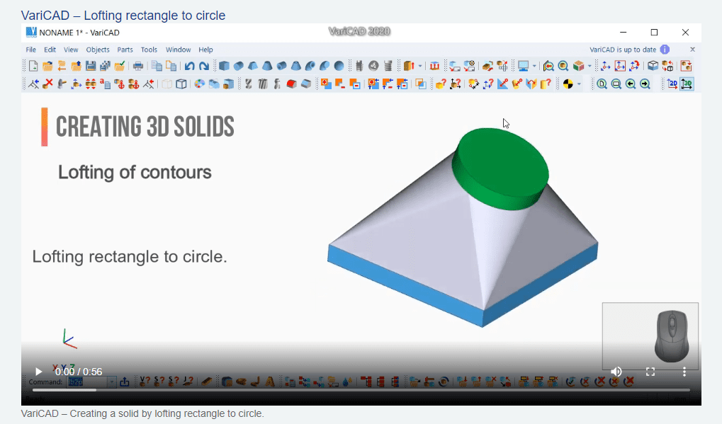
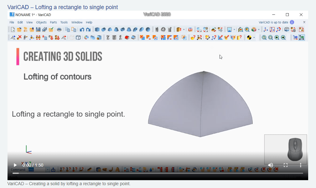
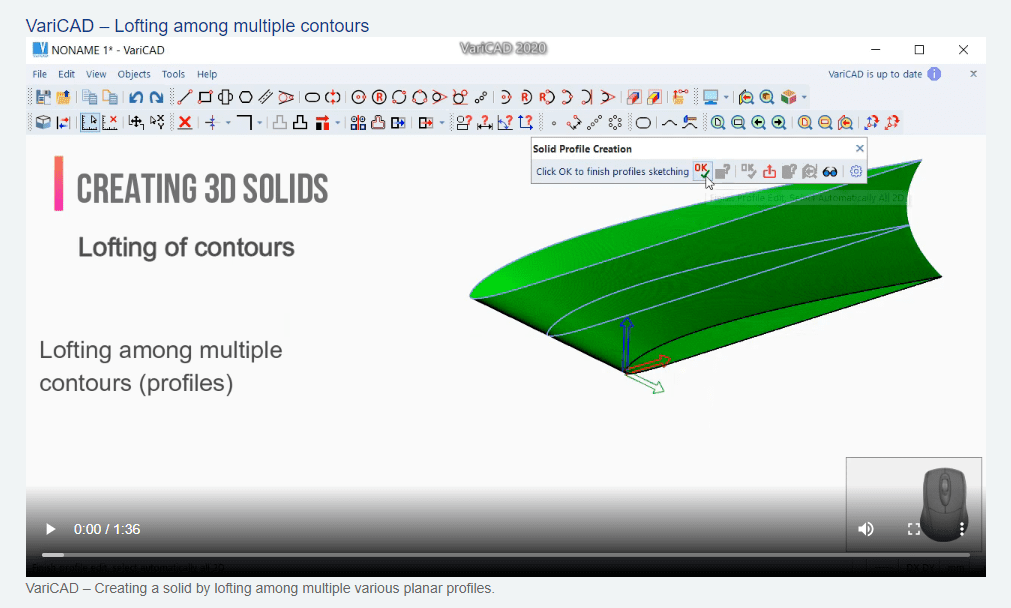
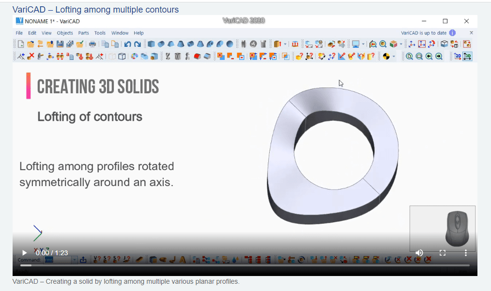
- 3D Modeling
- 2D Drawing and Editing
- Optional Support of Parameters
- Optional Support of Geometrical Constraints
- Shells Modeling, Pipelines, Wires
- Crash Tests (Interferences)
- 3D Assemblies and Groups
- Surface Development (Sheet Metal Unbending)
- Mechanical Part Libraries and Symbol Libraries
- Calculations of 3D Objects or 2D Sections
- BOM and Title Blocks
VariCAD - Designing Has Never Been Easier!
VariCAD - Designing Has Never Been Easier!
VariCAD is 3D / 2D CAD software primarily intended for mechanical engineering design. The comprehensive CAD software enables designers to quickly create, evaluate, and modify their models. The software is sold as one "fully loaded" package, with all features and functions, for one affordable price. VariCAD delivers an excellent performance-to-price ratio, making it one of the smartest choices on the market today.
ariCAD is available in English, German, Czech, Portuguese and Japanese versions. All features are included in one package (for one affordable price). For data exchanging, VariCAD uses STEP, STL, IGES, DWG and DXF file formats. The system fully supports Unicode
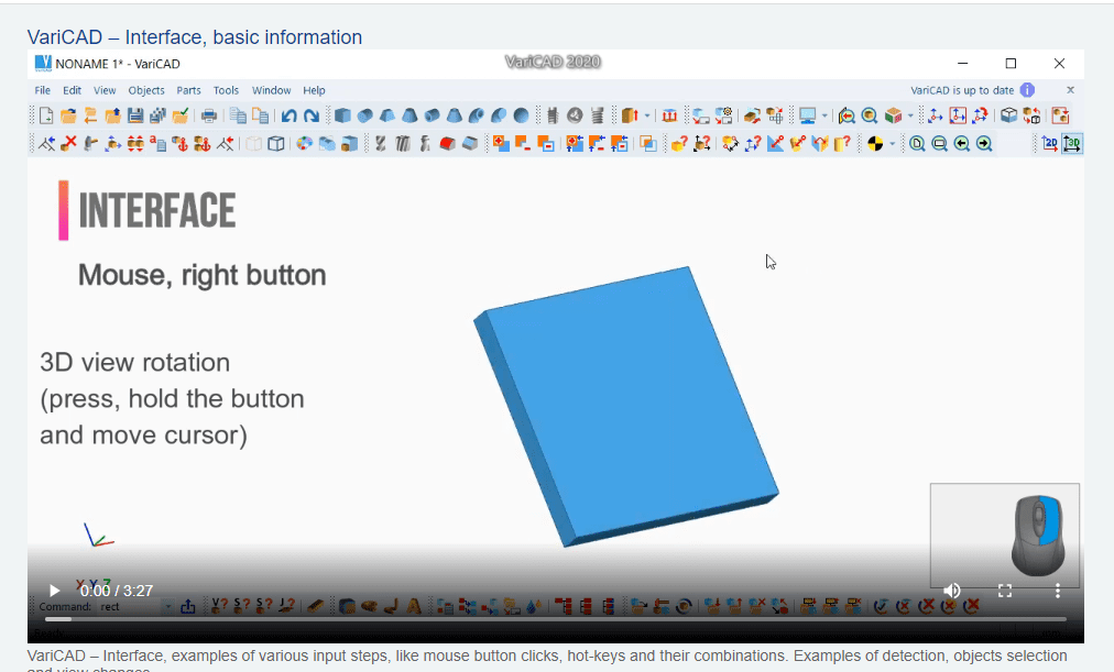
User Interface and System Environment
VariCAD's Graphical User Interface (GUI) has been designed to allow quick and intuitive 3D/2D orientation. It has been carefully tailored and tuned to reflect the thought process of a designer, so that ideas can be captured and communicated with a minimal number of steps. All commands were created with a focus on ease of use.
VariCAD - Designing Has Never Been Easier!
VariCAD - Designing Has Never Been Easier!
VariCAD - Designing Has Never Been Easier!
VariCAD - Designing Has Never Been Easier!
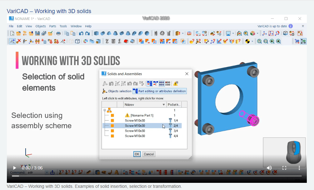
Assembly Tree Scheme - Video 1
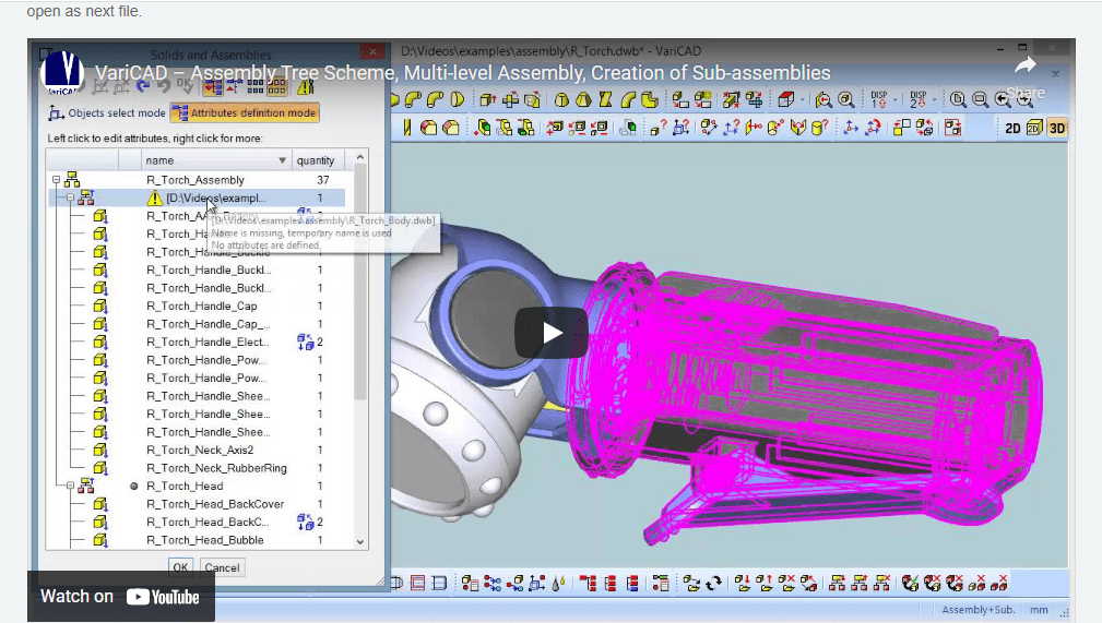
Sub-assemblies can be defined in separate files, or they can be defined from existing solids in assembly (like here). Sub-assembly is defined by set of solids and insertion point. In this example, an existing single-level assembly was divided into two sub-assemblies. Then, one of these sub-assemblies is open as next file.
Assembly Tree Scheme - Video 1
Sub-assemblies can be defined in separate files, or they can be defined from existing solids in assembly (like here). Sub-assembly is defined by set of solids and insertion point. In this example, an existing single-level assembly was divided into two sub-assemblies. Then, one of these sub-assemblies is open as next file.
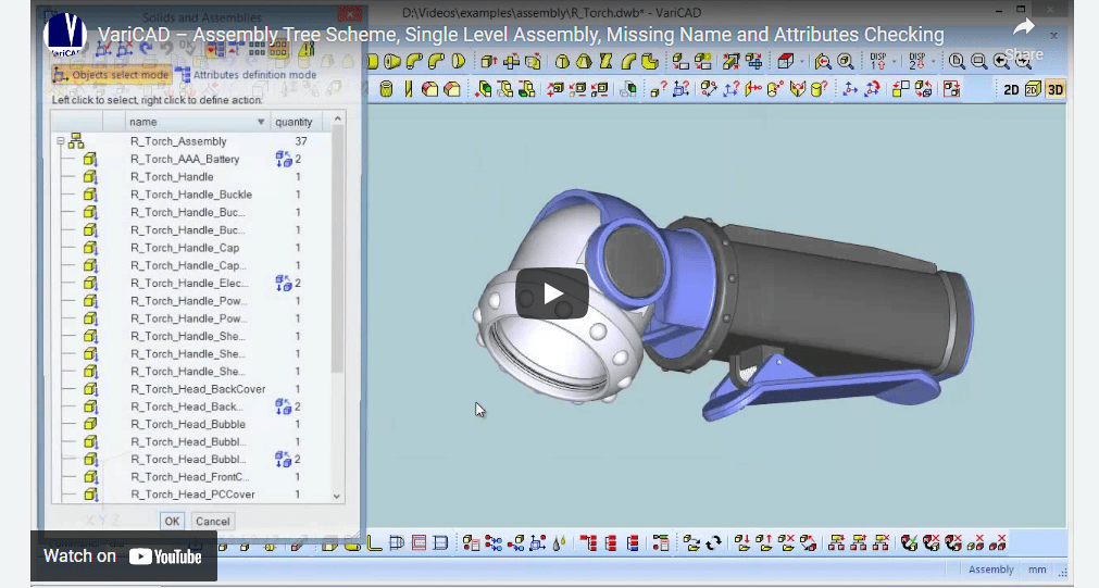
Assembly Tree Scheme - Video 2
Assembly Tree scheme is used for checking of missing names, missing mandatory attributes (like drawing number, material etc…) and for checking of missing links part-assembly. Assembly links can be established either by inserting parts into assembly file, or by exporting of plain solids from assembly into new part files (like in this example).